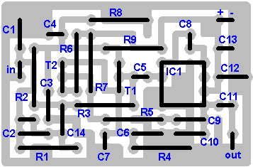
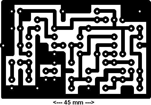
This is my schematic design of a Pulse Width Modulator DC/AC inverter using the chip SG3524 .
I have built this design and using it as a backup to power up all my house when outages occur.
If you like my work and intend to build the circuit don't forget to give me the 5 satrs :D and subscribe to me by clicking on the "follow" button so I know how many people benefit from the design, Thanks
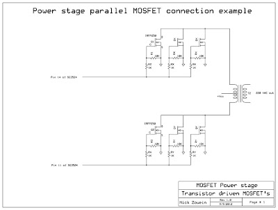
Notes:>The schematic circuit design is for a 250 watt output, while the pics are of my 1500 watts inverter that i built, to increase the power of the circuit you have to add more of the Q7 and Q8 transistors in parallel, each pair you add will increase your power by 250 watts, ex: to get 750 watts of power from the inverter you need to add in parallel 2 of Q7 and 2 of Q8 to the original design.
>If you increase the power transistors you have to enlarge the T2 transformer to match the new needs, the circuit's transformer is rated 25 amps to handle 250 watts of 220v, for every 1 additional amp you need on the 220v side you have to increase 10 amps on the 12v side, of course there are limits to the thickness of the winding so if you need more than 750 watts i recommend that you use a 24VDC supply instead of 12 volts:
DC voltage and Transformer "T2" winding recommendation:Power Supply Winding750w 12VDC P:24V "12-0-12" / S:220V
1500w 24VDC P:48V "24-0-24" / S:220V
2250w 36VDC P:72V "36-0-36" / S:220V
3000w 48VDC P:96V "48-0-48" / S:220V
3750w 60VDC P:120V "60-0-60" / S:220V
4500w 72VDC P:144V "72-0-72" / S:220V
5250w 84VDC P:168V "84-0-84" / S:220V
*The transformer should be "center tapped" at the primary side.
**You can make the secondary 110v if needed.
***The transformer in the pic is a custom made (48V center tapped / 220v ) 2000 watts, weights like 10 kilos.
>R1 is to set the PWM duty cycle to 220v. Connect voltmeter to the output of your inverter and vary VR1 till the voltage reads 220V.
>R2 is to set the frequency to 50 or 60 Hz (R2 range is between 40Hz to 75Hz), so guys that do not have a frequency meter are advised to blindly put this variable resistor mid-way which should drop you in the range of 50~60 Hz.
If you want you can substitue the variable resistor with a fixed resistor using the following formula: F = 1.3 / (RxC)
in our case to get a 50Hz output we remove both the 100K and the variable 100K both from pin 6 and we put instead a 260K fixed resistor and we leave the 0.1uF (the 104 cap) as it is, this change should give out a fixed 50Hz as per the formula :
1.3 / (260,000 ohm x 0.0000001 farad) = 50Hz
But in reality it will not exactly give 50Hz because the 260K resistor has a specific error value margin so does the capacitor, that's why i recommend a variable resistor so that accurate calibration can be achieved.
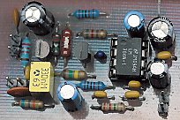
>Use either tantalum or polyester film "as in pic" for the 104 caps, ceramic disc caps change value once hot and this in turn changes the frequency of the inverter so they are not recommended.
>Pin 10 of the SG3524 can be used to auto shut down the inverter, once a positive voltage is given instead of negative to pin10, the SG3524 will stop oscillating. This is useful for persons wanting to add some cosmetic makeup to their inverters like overload cutoff, low battery cutoff or overheating cutoff.
>Wiring connections on the power stage side should be thick enough to handle the huge amps drain from the batteries. I marked them with dark black on the schema also I included a pic so you see how thick those wires must be.
>The design does not include a battery charger since each person will be building a custom version of the inverter with specific power needs. If you are ordering a custom made transformer you can ask them to take out for you an additional output wire on the primary side to give 14v (between point 0 and this new wire) and use it to charge a 12v battery, of course this needs a seperate circuit to control charging auto cut-off. But anyway this is not advisable because it will shorten the life of the transformer itself since using it as a charger will toast the enamel coating layer of the copper wires over time. Anyway .. YES can be done to reduce cost.
>A cooling fan will be needed to reduce heat off the heat sinks and transformer, i recommend getting a 220v fan and connecting it to the output T2 transformer, when you power up the circuit the fan will start this will always give you a simple way to know that 220v is present and everything is OK.. You can use a computer's old power supply fan if you like.
Note that the fan must suck air out from the inverter case and NOT blow inside, so install it the correct way or it will be useless.
Also note how I fixed both the heat sinks and where the fan is, in a way that the fan sucks hot air from like a channel between the 2 heatsinks.
>2 circuit breakers are recommended instead of fuses, one on the DC side and one on the AC side, depending on your design
Ex: for a 24vDC ( 1500 watts design ) put a 60Amp breaker on the DC side and a 6Amp on the AC side.
For every 1amp of 220vAC you will be draining like 8 to 10 Amps from the 12v battery, make your calculations !
> The 2 Heat sinks should be big enough to cool the transistors, they are separate and should NOT touch each other. "see the pics"
>I
mportant: If you're building a big design that uses more than 24VDC as power source, make sure not to supply the driver circuit with more than 24v maximum. (EX: If you have 4 batteries 4x12 = 48v , connect the v+ supply of the driver circuit to the second battery's (+) terminal with a thin 1 mm wire which is more than enough. this supplies the driver circuit with +24v while supplies the power transformer with +48v)
> "Optional" : Deep Cycle batteries are your best choice, consider them for best results ..
read more> Be cautious when building this circuit it involves high voltage which is lethal, any part you touch when the circuit is ON could give you a nasty painful jolt, specially the heat-sinks, never touch them when the circuit is on to see if the transistors are hot !! I ate it several times :)
> The optional "Low voltage warning" is already embedded in the PCB layout, you can disregard it and not install it's components if you do not needed. It does not affect the functionality of the main circuit.
> The Motorola 2N6277 is a heavy duty power transistor, it is used in many US tanks for it's reliability but unfortunately it is a very hard to find part, instead you can substitute each 2N6277 with 2 x 2N3773 or any equivalent.
> I've included an optional "Battery level indicator" circuit diagram that has 4 LEDs, you can see it installed on the front panel of my inverter pic, it is functioning great and shows precisely how much juice the batteries still have. I have included a small relay that is powered by the last LED to auto shutoff the inverter once last LED is off.
>Also included an optional "Overload circuit", it is very easy to build and can be calibrated to the desired overload current threshold cutoff point through the potentiometer VR1.


